- 您现在的位置:买卖IC网 > Sheet目录3862 > PIC18F45J11-I/ML (Microchip Technology)IC PIC MCU FLASH 32K 2V 44-QFN
PIC18F46J11 FAMILY
DS39932D-page 74
2011 Microchip Technology Inc.
PMDOUT2H(5)
—
PIC18F4XJ11
0000 0000
uuuu uuuu
PMDOUT2L(5)
—
PIC18F4XJ11
0000 0000
uuuu uuuu
PMDIN2H(5)
—
PIC18F4XJ11
0000 0000
uuuu uuuu
PMDIN2L(5)
—
PIC18F4XJ11
0000 0000
uuuu uuuu
PMEH(5)
—
PIC18F4XJ11
0000 0000
uuuu uuuu
PMEL(5)
—
PIC18F4XJ11
0000 0000
uuuu uuuu
PMSTATH(5)
—
PIC18F4XJ11
00-- 0000
uu-- uuuu
PMSTATL(5)
—
PIC18F4XJ11
10-- 1111
uu-- uuuu
CVRCON
PIC18F2XJ11
PIC18F4XJ11
0000 0000
uuuu uuuu
TCLKCON
PIC18F2XJ11
PIC18F4XJ11
---0 --00
---0 --uu
---u --uu
DSGPR1(6)
PIC18F2XJ11
PIC18F4XJ11
uuuu uuuu
DSGPR0(6)
PIC18F2XJ11
PIC18F4XJ11
uuuu uuuu
DSCONH(6)
PIC18F2XJ11
PIC18F4XJ11
0--- -000
0--- -uuu
u--- -uuu
DSCONL(6)
PIC18F2XJ11
PIC18F4XJ11
---- -000
---- -u00
---- -uuu
DSWAKEH(6)
PIC18F2XJ11
PIC18F4XJ11
---- ---0
---- ---u
DSWAKEL(6)
PIC18F2XJ11
PIC18F4XJ11
0-00 00-1
0-00 00-0
u-uu uu-u
ANCON1
PIC18F2XJ11
PIC18F4XJ11
00-0 0000
uu-u uuuu
ANCON0
PIC18F2XJ11
PIC18F4XJ11
0000 0000
uuuu uuuu
ODCON1
PIC18F2XJ11
PIC18F4XJ11
---- --00
---- --uu
ODCON2
PIC18F2XJ11
PIC18F4XJ11
---- --00
---- --uu
ODCON3
PIC18F2XJ11
PIC18F4XJ11
---- --00
---- --uu
RTCCFG
PIC18F2XJ11
PIC18F4XJ11
0-00 0000
u-uu uuuu
RTCCAL
PIC18F2XJ11
PIC18F4XJ11
0000 0000
uuuu uuuu
REFOCON
PIC18F2XJ11
PIC18F4XJ11
0-00 0000
u-uu uuuu
PADCFG1
PIC18F2XJ11
PIC18F4XJ11
---- -000
---- -uuu
PPSCON
PIC18F2XJ11
PIC18F4XJ11
---- ---0
---- ---u
RPINR24
PIC18F2XJ11
PIC18F4XJ11
---1 1111
---u uuuu
RPINR23
PIC18F2XJ11
PIC18F4XJ11
---1 1111
---u uuuu
RPINR22
PIC18F2XJ11
PIC18F4XJ11
---1 1111
---u uuuu
RPINR21
PIC18F2XJ11
PIC18F4XJ11
---1 1111
---u uuuu
RPINR17
PIC18F2XJ11
PIC18F4XJ11
---1 1111
---u uuuu
RPINR16
PIC18F2XJ11
PIC18F4XJ11
---1 1111
---u uuuu
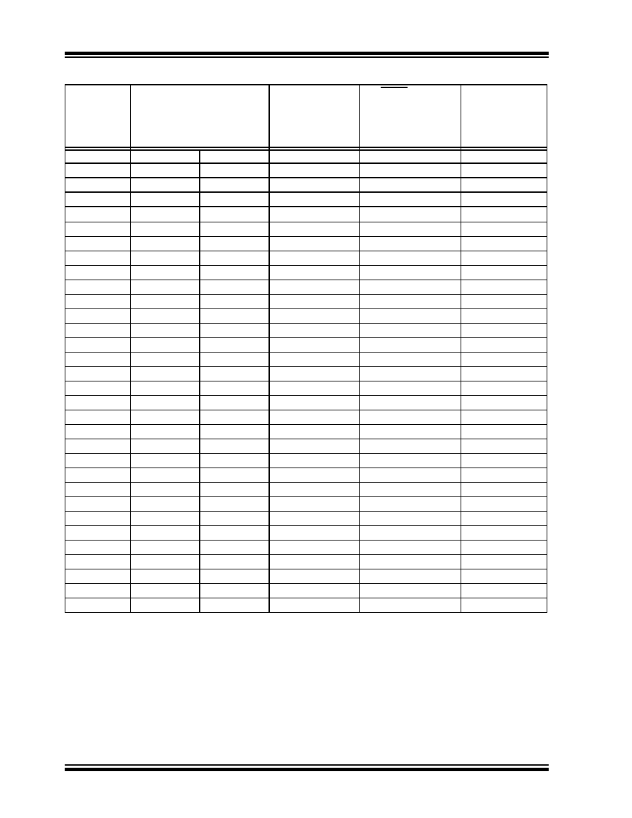
TABLE 5-2:
INITIALIZATION CONDITIONS FOR ALL REGISTERS (CONTINUED)
Register
Applicable Devices
Power-on Reset,
Brown-out Reset,
Wake From
Deep Sleep
MCLR Resets
WDT Reset
RESET
Instruction
Stack Resets
CM Resets
Wake-up via WDT
or Interrupt
Legend: u
= unchanged, x = unknown, - = unimplemented bit, read as ‘0’, q = value depends on condition.
Note 1:
When the wake-up is due to an interrupt and the GIEL or GIEH bit is set, the TOSU, TOSH and TOSL are
updated with the current value of the PC. The STKPTR is modified to point to the next location in the
hardware stack.
2:
When the wake-up is due to an interrupt and the GIEL or GIEH bit is set, the PC is loaded with the
interrupt vector (0008h or 0018h).
3:
One or more bits in the INTCONx or PIRx registers will be affected (to cause wake-up).
4:
See Table 5-1 for Reset value for specific condition.
5:
Not implemented for PIC18F2XJ11 devices.
6:
Not implemented on "LF" devices.
发布紧急采购,3分钟左右您将得到回复。
相关PDF资料
SFW15R-2STE1
SFW15R-2STE1-FFC/FPC CONN
PIC18F26J11-I/ML
IC PIC MCU FLASH 64K 2V 28-QFN
PIC18F46K20-E/ML
IC PIC MCU FLASH 32KX16 44QFN
PIC24FJ64GA002-I/SO
IC PIC MCU FLASH 64KB 28SOIC
PIC16C711-04/P
IC MCU OTP 1KX14 A/D 18DIP
PIC18LF26K22-I/SP
IC PIC MCU 64KB FLASH 28SPDIP
PIC18F25K80-I/SP
MCU PIC 32KB FLASH 28SDIP
DSPIC33FJ12MC201-I/SS
IC DSPIC MCU/DSP 12K 20SSOP
相关代理商/技术参数
PIC18F45J11-I/PT
功能描述:8位微控制器 -MCU 32KB Flash 4KBRAM 12MIPS nanoWatt RoHS:否 制造商:Silicon Labs 核心:8051 处理器系列:C8051F39x 数据总线宽度:8 bit 最大时钟频率:50 MHz 程序存储器大小:16 KB 数据 RAM 大小:1 KB 片上 ADC:Yes 工作电源电压:1.8 V to 3.6 V 工作温度范围:- 40 C to + 105 C 封装 / 箱体:QFN-20 安装风格:SMD/SMT
PIC18F45J11T-I/ML
功能描述:8位微控制器 -MCU 32KB Flash 4KBRAM 12MIPS nanoWatt RoHS:否 制造商:Silicon Labs 核心:8051 处理器系列:C8051F39x 数据总线宽度:8 bit 最大时钟频率:50 MHz 程序存储器大小:16 KB 数据 RAM 大小:1 KB 片上 ADC:Yes 工作电源电压:1.8 V to 3.6 V 工作温度范围:- 40 C to + 105 C 封装 / 箱体:QFN-20 安装风格:SMD/SMT
PIC18F45J11T-I/PT
功能描述:8位微控制器 -MCU 32KB Flash 4KBRAM 12MIPS nanoWatt RoHS:否 制造商:Silicon Labs 核心:8051 处理器系列:C8051F39x 数据总线宽度:8 bit 最大时钟频率:50 MHz 程序存储器大小:16 KB 数据 RAM 大小:1 KB 片上 ADC:Yes 工作电源电压:1.8 V to 3.6 V 工作温度范围:- 40 C to + 105 C 封装 / 箱体:QFN-20 安装风格:SMD/SMT
PIC18F45J50-I/ML
功能描述:8位微控制器 -MCU Full Spd USB 32KB 4KBRAM nanoWatt RoHS:否 制造商:Silicon Labs 核心:8051 处理器系列:C8051F39x 数据总线宽度:8 bit 最大时钟频率:50 MHz 程序存储器大小:16 KB 数据 RAM 大小:1 KB 片上 ADC:Yes 工作电源电压:1.8 V to 3.6 V 工作温度范围:- 40 C to + 105 C 封装 / 箱体:QFN-20 安装风格:SMD/SMT
PIC18F45J50-I/PT
功能描述:8位微控制器 -MCU Full Spd USB 32KB 4KBRAM nanoWatt
RoHS:否 制造商:Silicon Labs 核心:8051 处理器系列:C8051F39x 数据总线宽度:8 bit 最大时钟频率:50 MHz 程序存储器大小:16 KB 数据 RAM 大小:1 KB 片上 ADC:Yes 工作电源电压:1.8 V to 3.6 V 工作温度范围:- 40 C to + 105 C 封装 / 箱体:QFN-20 安装风格:SMD/SMT
PIC18F45J50T-I/ML
功能描述:8位微控制器 -MCU Full Spd USB 32KB 4KBRAM nanoWatt RoHS:否 制造商:Silicon Labs 核心:8051 处理器系列:C8051F39x 数据总线宽度:8 bit 最大时钟频率:50 MHz 程序存储器大小:16 KB 数据 RAM 大小:1 KB 片上 ADC:Yes 工作电源电压:1.8 V to 3.6 V 工作温度范围:- 40 C to + 105 C 封装 / 箱体:QFN-20 安装风格:SMD/SMT
PIC18F45J50T-I/PT
功能描述:8位微控制器 -MCU Full Spd USB 32KB 4KBRAM nanoWatt RoHS:否 制造商:Silicon Labs 核心:8051 处理器系列:C8051F39x 数据总线宽度:8 bit 最大时钟频率:50 MHz 程序存储器大小:16 KB 数据 RAM 大小:1 KB 片上 ADC:Yes 工作电源电压:1.8 V to 3.6 V 工作温度范围:- 40 C to + 105 C 封装 / 箱体:QFN-20 安装风格:SMD/SMT
PIC18F45K20-E/ML
功能描述:8位微控制器 -MCU 32KB Flash 1536B RAM 25 I/O 8B RoHS:否 制造商:Silicon Labs 核心:8051 处理器系列:C8051F39x 数据总线宽度:8 bit 最大时钟频率:50 MHz 程序存储器大小:16 KB 数据 RAM 大小:1 KB 片上 ADC:Yes 工作电源电压:1.8 V to 3.6 V 工作温度范围:- 40 C to + 105 C 封装 / 箱体:QFN-20 安装风格:SMD/SMT